In robotic extrusion the robot slows at corners while the extruder keeps its commanded speed, so the deposited bead changes. The process is hard to observe while it runs.
What I did
Built the sensing and logging setup, ran printing experiments, calibrated the stereo camera to the robot, profiled depth accuracy against distance, and benchmarked deep-learning models for bead-width measurement. Then built a closed-loop controller: a camera reads the bead width while printing, and the PC adjusts the robot's speed override through RSI every few milliseconds.
The print head
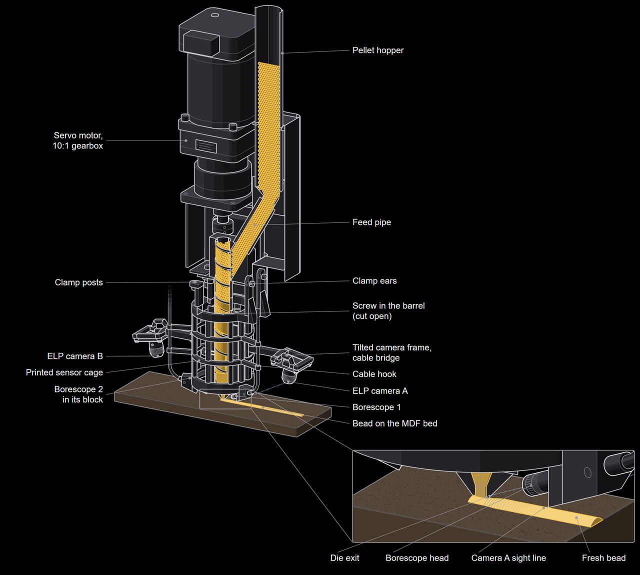
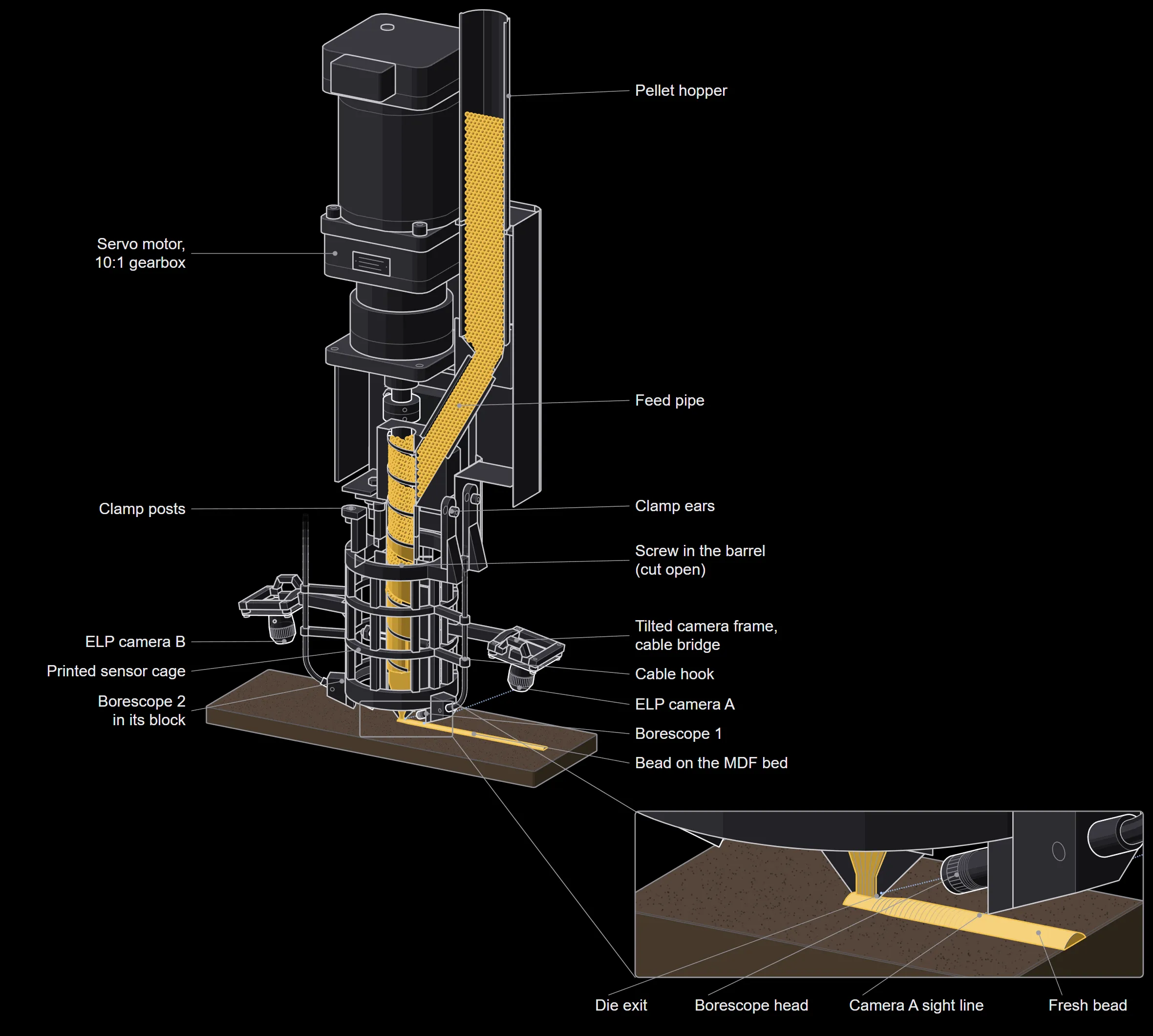
A single-screw pellet extruder on a KUKA KR10 robot arm, with a 3D-printed cage that holds cameras and borescopes near the nozzle. The drawing cuts the extruder open to show the screw carrying pellets down to the nozzle. It was drawn from a 3D scan of the extruder, the vendor's CAD model and the cage CAD; the inside of the screw channels is schematic.
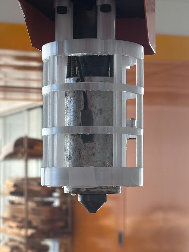
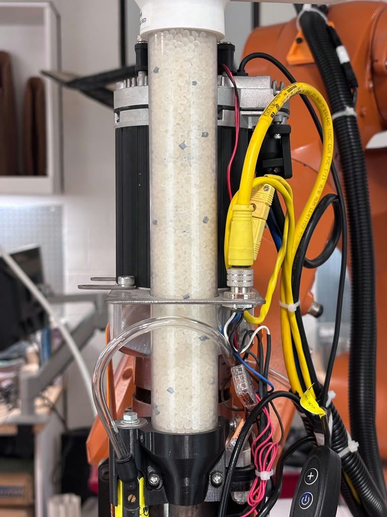
Drawing: the print head with its sensor cage. Gold marks the material, blue the cameras' sight lines. Open full sizeAn earlier version of the sensor cage on the extruder, October 2026.The pellet tube, motor and wiring on the robot arm, October 2026.
Code
The PC side of the loop is open source as a ROS 2 port, with a simulator of the robot controller and a replay of one logged print.
Result
Closed-loop prints ran in 2026; results are in preparation.
Role
Doctoral research. I instrumented the lab's KUKA KR10 pellet-extrusion cell with RSI telemetry, a stereo camera, a bead camera and a nozzle borescope on custom printed mounts, wrote a logger that records robot pose, speed and commanded extruder speed in sync with video, calibrated the camera to the robot, and trained a model that reads bead width from borescope images. The robot, extruder and base control chain were set up earlier in the lab.
Credits
Computational Tectonics Lab, University of Virginia; advisor Ehsan Baharlou.